SELECT LANGUAGE: 


Comparison Between Metal Plate & Ceramic Type Hvac Motor Control Resistors
Simply put, these are tailor made resistors having 3 distinct resistance values which translates into controlling the Blower Motor speeds of an Automotive Air-conditioner.
These resistors are mounted in the Air Flow of the Air-conditioner module and the reason behind this is, to keep the resistor as cool as possible.
In the case of a malfunction wherein the blower motor seizes, the resistor also has a dual purpose of being a safety device as it is fitted with a thermal fuse which will intervene and shut down the circuit
We have seen world-wide that these types of resistors are largely in two types: –
- Ceramic Type
- Metal plate Type
Geographically speaking it can be seen that in Europe Ceramic type is pre-dominant and in the Far East Metal plate type is pre-dominant.
Owing to this there is an ongoing debate among automotive manufacturers and HVAC module manufacturers as to which type is superior.
This article has been specifically written to explore the merits & demerits of both sides of the argument.
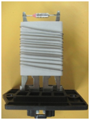
It would be a good starting point if one studied the internal construction of both types which is illustrated below:-
|
|
|
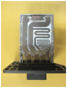
The metal plate type consists of a monolithic resistance alloy plate which has been punched out to create 3 different resistance values.
The advantage in this case is that the process can be automated as the alloy metal plate can be punched out.
The distinct disadvantage in this type of construction is that the designer has to make a compromise in the selection of the thickness of the metal plate as he has to obtain 3 different resistance values from the same plate and owing to this he is not in a position to select the optimum material and thickness for each individual resistance value. Therefore, there is an inherent issue of heating, which is detrimental to the life expectancy of the resistor.
The ceramic type resistor consists of a ceramic former on which the 3 different resistance values are obtained by winding 3 distinctly different wire gauges to obtain the 3 different resistance values.
The disadvantage in this construction is that it is more difficult to automate as compared to the metal plate type.
The distinct advantage in this type is that the designer can select and wind the optimum resistance alloy wire and gauge of wire hence leading to minimum heating.
Further, the fact that the wires are wound on to a ceramic former is another advantage as the -ceramic former helps dissipate the heat generated.
As far as the metal plate type resistor is concerned heat dissipation & insulation is aided by sandwiching the resistance element between 2 mica plates which is then placed inside an finned aluminium case and therefore these resistors greatly depend on the flow of the air from the blower to keep them operational as they tend to heat up very quickly which is also a problem when the ambient temperature is high especially in tropical countries.
In the ceramic type resistor as far as heat dissipation is concerned in addition to the ceramic former which aids heat dissipation, the resistors are normally coated with a fire retardant coating formulation which is UL approved.
Therefore, the ceramic type resistor due to superior heat dissipation leads to a resistor with a longer life expectancy.
We have tried to illustrate the advantages and disadvantages of both types and it is up to the designer to select a type which most suits his application.
Techno/Economic Comparison Between Silicon/Cement Coated Wire Wound Resistors And Ceramic Encased Resistors
Traditionally Wire Wound Resistors meant coated resistors of either silicon or vitreous enameled on a Ceramic body which was wound with resistance wire which was welded or soldered to the terminals and these types of resistors were termed as professional or industrial grade Wire Wound Resistors.
However in the mid 1970’s there was a demand for commercial grade wire wound resistors to meet the growing demand for a cheaper alternative to be used in the commercial or entertainment sectors
This demand was largely met by the introduction of ceramic encased resistors wherein the resistor core was an extruded fiber glass body which had resistance wire wound on it in a continuous process .These continuous fiber glass wound rods were cut to size and the terminals were crimped on to the fiber glass resistor core as opposed to the professional/industrial grade where the resistance wire was welded to the terminals .These fiber glass sub-assemblies were then inserted into a ceramic case and potted with a silicon resin infused potting mixture which contained inert fillers.
However with the constant escalation of the costs of ceramic products over the years the cost advantage of these ceramic encased resistors has eroded and this has narrowed to a point where many customers would now like to re-evaluate the decision as to whether to use a silicon/cement coated resistor or a ceramic encased resistor.
In order that the component user can make a comprehensive techno/economic decision, we at HTR, now give below a table showing the salient differences and advantages between the two technologies.
| Techno/Economic Parameter | Silicon/Cement Coated Resistor | Ceramic Encased Resistor |
|---|---|---|
| Moisture Absorption | Extremely limited | Should be moisture proof, provided the potting mixture is correctly utilized and formulated. |
| Tight Tolerances | Upto to even 0.05% | Limited to 5% at best. |
| TCR | Very low TCR’s as low as 10 ppm/°C are possible. | Due to the method of construction it is observed in practice that optimum TCR’s achievable would be at best 60 ppm/°C . |
| Load Life | Extremely Robust | Extremely Robust |
| Flammability | Fire Retardant Coatings are available which are now UL certified .(However under sustained overload conditions there is a possibility that the resistor may burst into flames momentarily which will immediately self extinguish) | It is Flame proof due to the nature of its construction. |
| Manufacturing Cost | Average due to low curing temperature of Silicon/Cement coating. | Higher as there is an additional process of potting the resistor in the ceramic case |
| Emission of Fumes | Very limited fumes | Very Limited fumes |
| Production Process (From an Environmental angle) | Good | Good |
| Non Inductive Winding | Possible | Not Possible due to nature of process |
| Pulse capability | Excellent | Fair |
| Power to size Ratio | Excellent | Fair |
For further information, please visit our website www.htr-india.com or contact us at info@htr-india.com
Why Are Capacitor Discharge Resistors Now Mandated As Essential Safety Device
In Electronics, Capacitor discharge resistors or Bleeder resistors are resistors connected in parallel with the output of a high voltage power supply circuit with the express purpose of discharging the residual electric charge stored in the filter capacitors of the power supply.
As an example, a switch mode power supply uses a bridge rectifier to convert AC Mains Power into DC at 320V (where the mains voltage is 220/240V) or 160V (where the mains voltage is 110/120V), before the voltage is reduced by the chopper. One or more Filter capacitors are incorporated to smooth the pulsating output voltage from the rectifier. Now these capacitors must necessarily store enough energy at this high voltage to power the load during the Zero crossings of the AC input.
Further, the capacitors chosen in many power supplies are designed to be large enough to supply the load during Power breakdowns lasting for a second or so.
This stored charge is often enough to deliver a lethal shock in devices such as Lasers, X-Ray machines, Radio transmitters and also the old style CRT screens.
It is most important that it must be recognized that this stored charge can remain in the capacitors for a significant period of time even after the unit has been turned off, and therefore poses a life threatening hazard for the user or maintenance personnel who may believe that because the device is turned off it is safe.
To meet the challenge of this safety hazard, it is necessary to discharge the capacitors after the power has been turned off and typically a large or high resistance value resistor is connected across the terminals of the capacitor.
So after the device is switched off, the charge on the capacitor will drain off through this Capacitor Discharge or Bleeder Resistor, thus rendering the device safe for servicing etc.
It is pertinent to note that when the device is ‘ON’ a small current flows through Capacitor Discharge/Bleeder resistor which results in the wastage of a small amount of power.
In order to reduce this power wastage it is necessary for the designer to select, an optimum resistance value due to the fact that there is a trade off between the speed at which the capacitor can be drained off and the wastage of power during normal operation.
The lower the resistance value of the Capacitor Discharge /Bleeder Resistor, the faster the bleed down rate but wastage of more power during normal operations and vice verse for a higher resistance value.
To meet this need, HTR provides a Capacitor Discharge/Bleeder Resistor which is so designed that the resistor can be mounted directly to the capacitors terminals and not through any connectors, thus eliminating the risk of the Bleeder resistor being disconnected accidentally.

HSRC Series

HSR Series
Types Of Fusible Wire Wound Resistors and Ordering Information Required
A fusible resistor is a tailormade dual purpose component –
- In normal conditions it functions as resistor
- In high overload/fault conditions it acts as a fuse/safety device
There are basically two types of fusible resistors:
- Tailor made fusible resistor to suit a customers particular application
- Safety fusible resistor
(a) Tailor Made Resistors
In order to correctly design a Tailor made fusible resistor to suit the customers specific application, the following data is required
- Power rating in terms of watts.
- Resistance in ohms.
- Tolerance.
- Maximum continuous working voltage across the resistor , at which the resistor must continue to function.
- Fusing Voltage – The voltage at which the resistor must fuse or blow.
- Fusing time – The duration within which the resistor must blow or fuse on being subjected to the fusing voltage.
- Frequency of Power source , voltage waveform.
- Brief details of the application.
In certain cases the customer must be made aware that the compromise inherent in the trade off between resistive and fusing function make certain exact combinations not possible. Having said this that does not mean that it is not possible to make a functional fusible resistor capable of that particular application.
(b) Safety Version Resistors
At HTR, special “Safety versions” are available in our FRS series and HFW series for resistance values => 10R where the resistor will fuse instantaneously when Mains Voltage is applied with no flame or explosion.

FRS Datasheet

HFW Datasheet
The FRS series “Safety version” will fuse when mains voltage 220/240V is experienced and the HFW series “Safety version” will fuse when mains voltage of 110/120V is experienced.
These “Safety versions” are suffixed with the alphabet ‘S’ after the HTR type to signify that this are safety fusible resistors.
Comparative Performance between Thick Film and Electron Beam Welded Metal Band Resistor Technologies when used in Automotive Applications.
These current sense resistors are predominantly used in automotive application in the DC/DC convertor output block and in battery management. The basic circuitry followed is that these low ohms resistors are connected in series with the load, and the potential difference between both terminals are measured by an IC to determine the quantum of current flow. The performance of IC’s available today has made great strides which enable them to measure current more accurately by being able to read ever diminishing potential differences.
The result of this is that by using ultra low resistance values it is possible to detect even large currents in excess 160 AMP, with lower power consumption as compared to devices being used at present. Using the older thick film technology, these low ohms resistors are made by screen printing the resistive element and electrodes on an alumina substrate and generally speaking these thick film resistors which are available today have resistance range in tens of milliohms. The electron beam welded metal band resistors have a very rugged construction where the different resistance alloys selected are welded to the copper electrodes. The very nature of the construction of these resistors contributes to excellent heat dissipation as compared to the thick film variety.
Using this technique it is possible to made devices with resistance range of several milliohms which mean a much lower resistance value as compared to thick film devices and with the characteristic of superior heat dissipation as compared to the thick film devices, hence lending itself to providing a smaller & more reliable device. Hence, the metal strip resistors offer higher power and very precise temperature co-efficient of resistance as compared to thick film devices.
Further since these electron Beam welded metal band resistors can be made having resistance value much lower than thick film devices, they have the added advantage over thick film devices by being able to exploit the property of the latest IC’s which can now measure even the smaller potential differences.
At HTR, being an IATF 16949:2016 company, we are committed to offering our automotive customers the full range of resistive devices using the latest electron beam technology to contribute to the quest of enhanced detection accuracy, reduction in the size of the devices and in conserving power consumption.
To this end we offer the following series.
Comparative advantage of Wire Wound Technology over Film Technology in Fusible Resistor applications
Fuse Resistors serve a dual purpose, as a resistor and also a fuse. They are designed so that they will open with a large surge of current without any flame or other untoward incident.Fusible film resistors are generally used for lower power requirements and applications where the overload and surge handling requirements are not too severe. Many power supply and control circuits need a more robust resistor and safety fusible wire wound resistors fulfill that need of being able to withstand higher power, higher short-term pulses and higher temperatures.Further using Wire Wound technology over Film technology, one can design a safety fusible resistor which fuses instantaneously in fault condition of the circuit and the same technology can be used to tailor the fusing performance characteristics to match the design requirements of many different end products.
Fusible resistors made by utilizing the Film technology are basically constructed by depositing a film either Thick Film or Thin Film resistive film, onto a ceramic core. Various resistance values are obtained by cutting the film in a spiral pattern using either mechanical cutting wheel or laser.
Fusible Wire Wound Resistors are made by winding a precisely selected resistive wire around the ceramic cor. By varying the diameter, length, alloy of the wire and the winding pitch the properties of the fusible wire wound resistor can be precisely tailored for a particular application.
Looking to the very nature of the two different technology constructions, it is evident that in the case of the film technology when the film fusible resistor reaches its fusing voltage/current the resistive film fractures which results in a different resistive path mostly the resistance value increases greatly and this is considered a fused film resistor as due to the greatly increased resistance value, the current that can pass is negligible.
Contrary to the above the fusible resistor made using wire wound technology has the distinct advantage that since the resistive element is a resistance wire, once the wire fuses there is no chance of any voltage/current being able to pass. Hence a wire wound resistor which is fused acts as a more reliable safety device as once it is fused no current or voltage can pass which could damage other expensive and critical components on the PCB, this is not the case in fusible film resistors.
Typical applications of Fusible Wire Wound Resistors include electric power tools, utility meters, communications equipments, kitchen appliances among others.
HTR, (an IATF 16949:2016 company) offers Fusible Wire Wound resistors which are UL 1412 recognized and serve as a reliable dual purpose component, of being a resistor in normal working condition of the circuit and in being a fuse in fault conditions.
To this end we offer the following series.
The FRS series is suitable for those countries where the mains voltage is 2
20/240V and the HFW series is suitable for those countries where the mains voltage is 110/120V.
Low Ohmic / Current Sense Resistors for Automotive Applications
The demand for these types of resistors has increased in the automotive sector with the proliferation of Hybrid and Electric cars and in the sector in general due to the enhanced level of computerization and sophistication of various control systems.To meet this enhanced demand, HTR has introduced a wide variety of Electron Beam welded current sense resistors which have very superior size to power rating ratio , Ultra Low ohmic values which help in reducing circuit power consumption.These resistors are high precision devices featuring low temperature coefficient of resistance (TCR) thus making them very suitable over other devices in harsh temperature environments.
The very nature of the physical configuration of these resistors having large copper terminals lend to rugged mounting, superior power to size ratio, both qualities which are considered so desirable in automotive applications.
It is note worthy to point out that these Electron Beam shunts are now available from 2 watt rating to 10 watt rating and can dissipate in some cases over 200 amps without significant heating.
The HTR series which support this application are in a variety of sizes from 2512 to 5930 and physical configurations to suit most PCB design requirements.
A significant proportion of our production is for the automotive industry and our IATF 16949:2016 certification reinforces this.
Use of Current Sense Resistors for Battery Management in Automotive Applications.
In automotive applications the requirement of electronic circuits for battery charge monitoring for the detection of the remaining battery level and over current protection has now seen a steep spike in demand with the recent proliferation of Hybrid and Electric vehicles.Typically these low ohm resistors are used in this applications for current sensing by connecting them in series with the load and the potential difference between both terminals is measured by an IC to determine the current flow. In recent years IC performance has improved substantially leading to vastly improved current detection accuracy by being able to measure even tiny potential differences.In order to exploit this feature, it necessitated the use of Ultra Low Ohmic Values which are capable of detecting large current with lower power consumption as compared to the resistive devices being used at present.Recent innovations have shown that Electron Beam Welded metal strip resistors offer Ultra Low Resistance values, enhanced Power Rating upto even 10 watts at negligible thermal dissipation as compared to thick film products .Being committed to being a partner to the automotive industry, HTR has introduced the following series to support the ever rising demand for this application and our IATF 16949:2016 certification reinforces this commitment.
Application / Design Notes on Selection of Wirewound Resistor
BASICS
Simply put, a resistor is an electronic component connected into an electrical circuit to insert a specific resistance. Resistance is measured in ohms and as per ohms law, the current through the resistor will be directly proportional to the voltage across it and inversely proportional to the resistance. As the current flows through the resistor, heat is produced which makes the temperature of the resistor to rise above the ambient temperature.
Now whether a particular resistor can be used in a specific electrical circuit is its ability to dissipate the heat generated without physical deterioration and within the temperature limits of that particular circuit.
Resistors are rated to dissipate a given wattage without exceeding the declared “hot spot” temperature. This is largely determined by the size and materials used in the construction of the resistor and this is called “Free Air Watt Rating” or “Full Rating” or “Maximum Power Rating”.
In some cases the conditions actually encountered deviate from the standard conditions and affect the temperature rise which determines whether that particular resistor can be used or not in a particular application.
SELECTION PROCESS – Stepwise Guide
- Decide the resistance value required
The following formulae derived from Ohms law can be used for this purpose:R = V/I or I = V/R or V = I x R where,(R is resistance in ohms, V is voltage in volts and I is current in Amperes)
- Decide the watts (Power) to be dissipated by the resistor
W = I² x R or W = V x I or W = V²/R where,(W is Power Rating / Wattage in watts, I is current in Amperes, R is resistance in ohms and V is Voltage in volts.)
Note: Whilst the power rating in watts can be theoretically determined as above, a note of caution is now introduced – It is important that the actual current that will be drawn is used in the determination of the power rating / wattage of the resistor.
Small increases in current or voltage e.g. 20% translate into 44% increase in the power rating / wattage required to dissipate the increased current / voltage within temperature rise limitations. At this point it is also worth mentioning that the designer should also make allowance for the maximum possible line voltage.
- Decide the correct physical size (“watt size”) based on the following parameters: watts, volts, temperature that can be permitted in the particular circuit and mounting consideration.
The wattage rating of a resistor as established under specified standard conditions is defined as “Free Air Rating” (Maximum Power Rating).
The following method is broadly used to determine “Free Air Rating” based on the methods followed by “National Electrical Manufacturers Association” – USA (NEMA), “Underwriters Laboratories Inc.” (UL) and US MIL – R26 – US Military Specification for wirewound resistors.
In US MIL – R26, there are mainly 2 broad characteristics of resistor types – characteristic ‘V’ and characteristic ‘U’.
Characteristic ‘V’ resistors are required not to exceed a maximum operating temperature of 350°C, which corresponds to a maximum temperature rise of 325°C at ambient temperature 25°C.
Characteristic ‘U’ resistors are required not to exceed a maximum operating temperature of 275°C, which corresponds to a maximum temperature rise of 250°C with ambient temperature 25°C.
The temperature is normally measured on the body of the resistor, suspended in free still air space with unrestricted circulation of air. When current passes through a resistor, heat is generated and the temperature stabilizes when the sum of heat loss (by termination conduction, radiation and convection)equals the heat input rate (created by passing current proportional to wattage).
By rule of thumb, the larger the resistor, hence greater the area for heat dissipation, the lower the temperature rise.
Having said this, it must be admitted that certain other factors such as thermal conductivity of the ceramic core, type and gauge of resistance wire selected and the heat-sink effect of the type of mounting all influence the selection of a resistor to be considered having “acceptable service life”.
Further consideration must be given in case the resistor will be operated in elevated ambient temperatures higher than 25°C or 30°C and the power rating must be derated as per the derating curve provided with each HTR series.
For the design engineer’s general guidance, we give below the temperature rise that is generally observed on silicon coated axial resistors (ambient temperature of 30°C) at Maximum Power Rating / Free Air Rating.
|
Maximum Power Rating
(30°C ambient) |
Temperature Rise on
Body of Resistor |
Temperature Rise on
Termination of Resistor |
| 1 W | 50°C to 80°C | 35°C |
| 2 W | 60°C to 90°C | 37°C |
| 3 W | 65°C to 95°C | 42°C |
| 4 W | 80°C to 110°C | 45°C |
| 5 W | 100°C to 130°C | 45°C |
| 6 W | 105°C to 135°C | 46°C |
| 7 W | 125°C to 155°C | 50°C |
| 10 W | 140°C to 170°C | 46°C |
| 15 W | 155°C to 185°C | 52°C |
Absolute temperature can be arrived at after adding the prevalent ambient temperature at time of test to the temperature rise figures provided.
These figures are given to merely serve as a guide to a design engineer and must be verified in actual practical conditions by the design engineer before selection and use of a particular resistor.
- Decide the actual resistor to be used: based on actual practical considerations
Having determined the Wattage / Free Air watt rating on theoretical basis, the designer must now take the following factors into account when deciding on the actual resistor to be used in the application, as all these factors will influence the temperature rise:
- The influence of Ambient Temperature: All the components of an electronic circuit have their own limitations as to the maximum temperature at which they can reliably function. The temperature that the component rises to in service is the sum of the ambient temperature plus the temperature rise due to heat dissipated by each component during operation. Now some devices can tolerate elevated temperatures whilst others cannot.
Wire wound resistors can operate fairly reliably at reasonably elevated temperatures, so in order to ensure that the heat generated by the resistor is minimized, the designer may move to a higher power rating from the theoretical calculation to minimize the temperature rise and minimize the effects of heating on other devices which are heat sensitive in the circuit.
- The design of the Enclosure: The walls of the enclosure form a thermal barrier, preventing heat from escaping and preventing the outside air from entering and providing cooling. Hence, due care must be given to the optimum design / orientation of the ventilation openings of the enclosure.
- Spacing: In case due to design limitations, if heat generating components are bunched together, they will show a higher temperature rise due to heat received by radiation from each other. Therefore it is prudent if at all possible that the designer tries to prevent bunching of heat generating components and if this is not possible, moves to a higher power rating to minimize temperature rise.
- Surges: In certain applications for e.g. typically motor controllers, the resistors do encounter surge conditions which if not properly managed and taken into account at the time of designing the resistor, will lead to resistor failure.
A “Surge” occurs over such a short period of time, in the case of capacitor charge / discharge < 1 msec and in the case of motor start-up < 0.5 sec, that the substrate plays no role in heat dissipation and the energy must be completely absorbed by the resistive element itself. Please refer to the section “Pulse/Surge Capability of Resistors” provided in this catalog.Hence surge conditions, if any must be taken into consideration at this stage to determine the correct resistor for that application.
- Forced Air Circulation: In cases where the apparatus in which the resistor is mounted is heat sensitive or for certain reasons resistor used is of a lower than optimum wattage for that particular application, forced air circulation removes more heat in a shorter time than natural convection and is advised in the circumstances enumerated above.
- Derating: It is always advisable that a resistor should be derated and not operated at its actual power rating for long term reliability.
Please refer to the section “Rating versus Life” in the “Customer Assurance” section of this catalog. Suitable derating also contributes greatly to the minimization of “Drift Underload” phenomena observed in change in resistance value when a resistor is in operation.
- Higher Resistance Value: In order to achieve higher resistance values, the diameter of the resistance wire wound on the substrate is a very fine gauge, sometimes as little as 0.016mm, hence for maximum reliability it is suggested that the designer opts for a higher power rating if size is not a constraint in order to reduce the temperature rise.
- High Frequency Circuit: Wire wound resistors may be effectively used in circuits with frequency upto 50KHz when non inductively wound by the ‘Aryton-Perry’ method of winding.
For further details on this subject, please refer to the section “Wire wounds and their limitations when used in a high frequency circuit” in the “Customer Assurance” section of the catalog.
- The influence of Ambient Temperature: All the components of an electronic circuit have their own limitations as to the maximum temperature at which they can reliably function. The temperature that the component rises to in service is the sum of the ambient temperature plus the temperature rise due to heat dissipated by each component during operation. Now some devices can tolerate elevated temperatures whilst others cannot.