Type
Internal HTR reference for a certain component, to be used along with series for ordering.
Series
Collection of types with identical constructional features and technical data.
Physical Configuration
Physical style / appearance and dimensions of the component.
Power Rating
Electrical power, defined by current and voltage, a resistor can bear continuously at a given ambient temperature – Normally at 25°C, 40°C or 70°C.
Resistance Tolerance
The allowable deviation from nominal resistance value at the moment the component is received. Possible subsequent resistance changes due to electrical, climatic or mechanical stress are not included in this.
Temperature Characteristic of Resistance (Temperature Co-efficient)
Indicates the change in resistance value, which is largely determined by materials and styles, for every degree change in ambient temperature. This change is usually expressed in parts per million per degree Celsius (ppm/°C). Note: This change in resistance value is reversible.
Limiting Voltage / Voltage Rating / Maximum Continuous Working Voltage
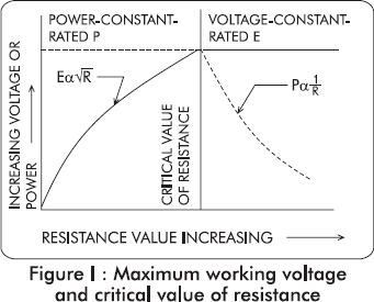
Limit for the voltage that may be continuously applied to the resistor. This voltage can be calculated using the formula given below:

Where,
- V = Rated DC or rms continuous working voltage,
- P = Power rating in watts &
- R = Nominal resistance in ohms.
Note: Since wire wound resistors do not exhibit the phenomenon of deterioration of the resistive element due to extreme voltage stress which causes conduction from normally non conductive materials in film resistors, hence maximum voltage rating are not normally specified in wire wound resistor datasheets and are governed by the above formula.
Critical Value of Resistance
For a given voltage rating / limiting element voltage and a given power rating in watts, there is only one value of resistance that will dissipate full rated power at rated voltage. This value of resistance is commonly referred to as the “Critical value of resistance”. For values of resistance below the critical value, the maximum (element) voltage is never reached and for values of resistance above critical value, the power dissipated becomes lower than rated. Figure I as given illustrates this relationship. In common parlance, it could be stated that critical value of resistance is that resistance value at which the rated voltage is equal to the “limiting element voltage”.

Voltage Proof or Dielectric Withstanding Voltage
This test demonstrates the ability of the dielectric or the insulation of the resistor to withstand a prescribed voltage typically 500V or maximum continuous working voltage x 2, applied between the body and both terminals tied together and there should be no untoward effect on the insulation.
Insulation Resistance
The DC resistance measured between both terminals tied together and the body of the resistor on being given a prescribed voltage, expressed in MΩ.
Short Time Overload
This test checks the deviation / change in resistance, usually irreversible, which occurs when a resistor is subjected to a prescribed overload voltage for 5 seconds.
Climatic Category
It establishes the lowest and highest temperature as well as the duration of the humidity testing. This category temperature and duration varies from standard to standard and from one type of the resistor to another.
Damp Heat, Steady State
This test specifies the permissible irreversible resistance change after defined climatic stress. The test procedures for administering the defined climatic stress are given in different standards such as MIL, IEC, JSS and JIS.
Load Life or Endurance
The relative irreversible resistance change after a specific testing time. Normally it is related to administering limiting voltage intermittently at 70°C ambient temperature and 1000 hour test duration.
Load Life or Endurance
The relative irreversible resistance change after a specific testing time. Normally it is related to administering limiting voltage intermittently at 70°C ambient temperature and 1000 hour test duration.
Temperature Range
The minimum and maximum ambient temperatures between which the component may be used with suitable derating as per derating curves provided with each series.
Hot Spot Temperature
The maximum temperature measured on the body of a resistor due to both internal heating and the ambient operating temperature. This hot spot temperature is determined by the thermal limits of the materials used and the design. Hot spot temperature is also defined as the temperature on the derating curve at which the resistor is derated to zero power.
Derating Curve / Rated Ambient Temperature
The power rating of a resistor is based on a certain temperature rise from an ambient temperature of a certain value. If the ambient temperature is greater than this value the amount of heat that the resistor can dissipate is correspondingly reduced and therefore it must be derated because of temperature. The extent to which the resistor should be derated in relation to ambient temperature is illustrated in the respective “Derating Curve” charts provided with each series.
Non Inductive Resistors
All resistors have capacitance and inductance as well as pure resistance and these factors can become significant at high frequencies.
For wire wound resistors inductive effects are predominant in low resistance value resistors [below 1K0] and capacitive effects become predominant in higher resistance values.
At HTR specialized winding techniques are used in the manufacture of our low inductance resistors so that these effects are reduced considerably. Also with the introduction of ceramic encased resistors with alloy ribbon elements, the problem of inductance due to winding has been nearly eliminated. Please refer to the current sense section for these new types.
Resistance to Soldering Heat
The normally irreversible change in the resistance value during the process of soldering.
Terminal Tensile Strength
The outer limit of the tensile force that can be applied to the terminal of the resistor.
Standards
These are written documents of norms, standard specifications and test methods which are nationally or internationally known for a given series of components. For fixed wire wound resistors the following standards normally apply, depending on type and construction.
| India JSS 50402 | USA MIL – R26 | EEC IEC – Pub 266 | Japan JIS – C6401 |


