HTR’s reliability testing facility is fully alive to the fact that its work in assuring quality can only be judged successful if it is converted to customer assurance.
Customer confidence will always be retained if the correct resistor is used in the way it is designed to be used. Towards meeting this objective the quality assurance team of HTR has put together a small guide.
OPTIMUM UTILISATION GUIDE FOR RESISTORS
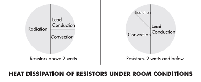
- Improper heat dissipationis the predominant contributing cause of failure for any resistor type; consequently, the lowest possible resistor surface temperature should be maintained. The chart given below illustrates the manner in which heat is dissipated from fixed resistors in free air.

The intensity of radiated heat varies inversely with the square of the distance from the resistor. Hence maintaining maximum distance between heat generating components serves to reduce cross – radiation heating effects and promotes better convection by increasing air flow.
Towards promoting better use of resistors, given below is A GUIDE FOR RESISTOR MOUNTING
- Maintain lead length to a minimum. [Note: Where low temperatures are present, leads should be offset (bent slightly) to allow for thermal contraction]
- The mounting of close tolerance and low resistance value resistors require special precautions (i.e., short leads and good soldering techniques) since the resistance of the leads and the wiring may be as much as several percent of the resistance of the resistors.
- Maintain maximum spacing between resistors.
- For resistors mounted in series, consider the heat being conducted through the leads to the next resistor.
- Large power units should not be mounted directly on to the PCB – try to select physical configurations which provide a stand-off.
- Large power units should be mounted to chassis wherever possible – mainly applicable in the case of 35W and above in tubular style.
- To provide for the most efficient operation and even heat distribution, power resistors should be mounted in a horizontal position.
- Consider levels of shock and vibration to be encountered. Where large resistors are concerned, the body must be restrained from movement.
- Wire wounds and their limitations when used in a high frequency circuitWire wound resistors have inductive and capacitive effects and are unsuited for use above 50kHz even when specially wound by the Aryton- Perry method. Wire wounds also usually exhibit an increase in resistance with high frequencies because of the &skin& effect.
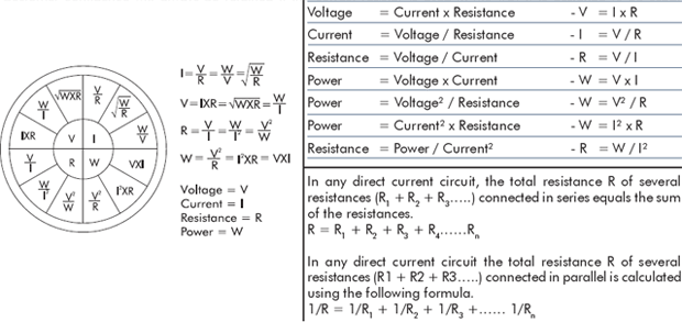
- The selection of a particular resistor for a particular circuit is often the result of a trade-off between the actual parameters required and the realities of the product being designed in terms of size or costs.In order to help the designer make a cost effective practical decision, the following &Rating versus Life& material being offered may be appreciated.A good rule to follow when choosing a resistor size for equipment that must operate for many thousands of hours is to derate it to one half of its nominal power rating. Thus, if the self generated heat in the resistor is 1/3 watt, do not use a 1/2 watt resistor, but rather 1 watt size. This will automatically keep the resistor cool, will reduce the long term drift, and will reduce the effect of the temperature co-efficient. In equipment that need not live so long and must be small in size, this rule may be impractical and the designer might have to compromise to some extent. In short, a &cool& resistor shall generally last longer than a &hot& one and can absorb transient overloads that might permanently damage a &hot& resistor.The designer would find it fruitful if the information provided above is read in conjunction with the section titled – Application / Design Notes on Selection of Wire Wound Resistors.IMPORTANT FORMULA’S DERIVED FROM THE APPLICATION OF OHMS LAW ARE REPRODUCED BELOW FOR THE CONVENIENCE OF THE DESIGNER IN HIS QUEST FOR THE CORRECT RESISTIVE DEVICE FOR HIS APPLICATION.
Ohms Law

Joules Law
- When current passes through a circuit, heat is generated. This heat (energy) is expressed in joules and calculated by the following formula:
- Energy (Joules) = I²R x TWhere ‘I’ is the current in Amperes, ‘R’ is resistance in ohms and ‘T’ is time expressed in seconds.
- Power Rating or Wattage can also be calculated by the following formula:
W = J(Energy) / T(seconds)


