HTR offers a very wide range of Low Ohm resistors for Current Sensing applications as given below:
- Axial Style (OA Series)
- Vertical / PCB Mounting Style (OP Series)
- Vertical / PCB Mounting Style – Punched out, Monolithical construction (OF series)
- Axial Style (HEAL Series) Square Cross Section
- Axial Style (RL Series) Cylindrical / Round Cross Section
- Surface Mount Style HSVALS / RLS Series / HCALS series.
- Axial Style (HCAL Series)
- Vertical / PCB Mounting Style (HMVL Series)
1. Open Frame
2. Ceramic Encased
3. Cement Type
4. Silicone coated (OFSC Series) High Power and 4 Terminals
These devices have emerged to provide a non inductive Low Ohm Resistor for current sensing which can also tolerate high impulse current. They are manufactured from Electrical Resistance Ribbons / Strips which are selected on the basis of specific parameters such as Resistance Value, Thermal Conductivity & TCR.
NOTES / HINTS TO BE TAKEN INTO ACCOUNT WHEN USING / DESIGNING AXIAL STYLE / CURRENT SENSE RESISTORS.
Tin plated copper terminals are welded to the resistive element & the tin plated copper terminals are then soldered to the PC Board.
Due to the nature of this assembly, the following notes should be read carefully, so that the device can be effectively utilized.
1. THE RELATIONSHIP / EFFECT OF THE INHERENT RESISTIVITY OF THE COPPER TERMINALS IN RELATION TO THE OVERALL RESISTANCE OF THE DEVICE
If the diagram given below is studied, it would be observed that when the resistor is supplied from the factory, its resistance value is checked over the centered length which is shown in the diagram as LM.
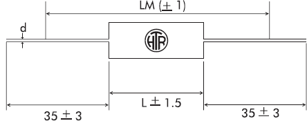
If however, during application the length of the copper terminations differs from the centered length “LM” as shown in the catalogue, the influence / resistivity of the copper lead wire of 0.4mΩ / cm must be taken into account, if the Φ0.8 mm copper lead is used.
2. THE RELATIONSHIP / EFFECT OF THE COPPER TERMINATIONS ON THE TCR / TEMPERATURE COEFFICIENT OF THE RESISTOR.
Generally speaking, the temperature coefficient of the resistive elements which are used in these resistors is around 140ppm/°C.
However, it is very important to remember that the copper terminations form part of the effective resistance and they influence the temperature coefficient between the contacts.
A general Thumb Rule which should be noted / observed is as follows:
- Higher the resistance value, less the influence of the copper terminations and lower the TCR.
- Lower the resistance value, higher the influence of the copper terminations and higher the TCR.
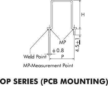
In case, the TCR is of prime importance in a particular application, it would be better for the designer to opt for a vertical mounting / PCB style resistor for example, the OP series or HMVL series where the influence of the copper lead wire is almost eliminated.
The diagram given below illustrates this point as it shows clearly that the measurement points & the weld points are the same, hence eliminating the effect / influence of the copper lead wire:
The OF series due to it’s monolithical construction offers, the most accurate reading of TCR provided it is soldered properly.
3. OWER RATING & CURRENT RATING / LIMITATIONS IMPOSED DUE TO MATERIALS USED.
Generally speaking, these resistors are very robust and are capable of handling power / current in excess of their declared / rated power rating as shown in the catalogue.
However, current rating can be of concern in overload / pulse conditions.
Since, the current limit is normally determined / defined by the current density and since 100A per mm2 are considered the upper limit in power electronics, therefore a 0.8mm copper lead wire would have a current limit of 50A.
Further, since the long term reliability of the resistor should be of ultimate concern to the user / designer, it is also important to remember that the welding junction between the copper lead wire & the resistance alloy should not carry more than 20A on a continuous basis for 0.8mm terminations.
Therefore, it would be prudent for a designer to ensure that the following current limits are not transgressed for the following terminations:
| Termination Φ | Current on continuous basis | Impulse Current |
| 0.8mm | 20Amp | 50Amp |
| 1.0mm | 31Amp | 78Amp |
| 2.0mm | 125Amp | 310Amp |
HTR’s RL series has been recently developed to provide an economic & superior replacement to the moulded resistors available so far.
The moulded resistors power rating is determined / limited by the maximum temperature of the moulding material and overheating may cause carbonisation of the plastic which could cause a short circuit.
The RL series offers the same size as the moulded resistors with the built in advantage that the moulded material is replaced by a cylindrical ceramic case and due to this the dis-advantages of the moulded resistors are totally eliminated.